BUILDING A STEEL FRAME
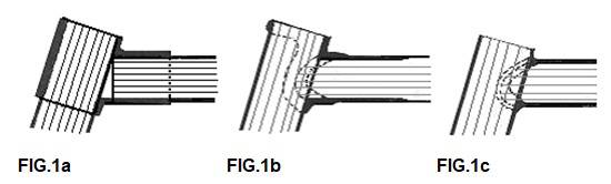
Real classical steel frames are built with lugs (brazing parts). The oldfashioned clunckerbike was made with thick tubes and heavy sandcast lugs. The tubes could be cut off straight and needed no mitering or filing (see FIG.1a). Using thin tubing would lead to cracks at the edge of the lug, so they started to make thin lugs out of steel sheets, that would be cut, pressed and welded . Often the fitting was not great, but you could use light tubes and lugs (see FIG.1b). Now mitering was important to create a strong joint; it is even more important in lugless construction (see FIG.1c) ! Modern cast lugs are made with the lost-wax-procedure (Italian: microfusione, in English: investmentcasting); this is an expensive production process. If the fitting is very thight the builder should use a high silvercontent brazing material; this should also be used with stainless steel and lugs. Using pressed steel lugs had the advantage the builder could alter the angles 3 to 4 degrees; for cast lugs this is only one degree. The craftsmanship of the builder is partly altering of the lugs! In factories the building of a lugged frame is often done this way:
The tubes are cleaned, cut to size and mitered. The tubes and lugs mounted together in an iron jig.. A small hole is drilled through the lugs and tubes and a small steel pin is pushed in. Some builders use more fixation and braze or TIG-weld the tip of the lugs. Next each joint is heated with an oxy-acetylene torch and brazed lug by lug . The big jig might transport the heat of the frame so it cools rather quickly. We don't like this, because the fast cooling might harden the steel. Small builders often use simple jigs or even none....
21.18 Framebuilding in England around 1979.
25.19 The Taylor brothers, around 1985
3.17 Building a retro Colnago around 2010
Dispite a jig I will check every joint after brazing. If necessary I will align; who waits until the frame is complete must use more force; and correcting one tube might introduce another fault. Of course there are tolerances aligning a frame. Without expensive tools you can measure to about half a degree and ± 1 mm accurate. When you use wide tires there will be no problem. Narrow tires or tubulars are more sensitive, and a small divergence can induce bad bevaviour on the road. Especially the shimmy is notorious. If a bike reallly starts pulling to the right or left, the divergence is much larger. First check the wheels if the rims are in the middle of the wheel; then check if the plane of both wheels form one plane in the middle of the frame.
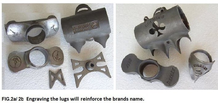
By engraving the lugs and using specific brazing parts like the butterfly bridges of Gazelle, the company makes the frame easy to recognise. The cloverleafs of Colnago and the deer on the Gazelle frames are good examples of this praxis.
A steel tube will go into a bath of preservation oil as the last step in the production process. So the tube must be cleaned before building the frame. Take a cleaning rag with some degreaser and clean the tube inside and outside.
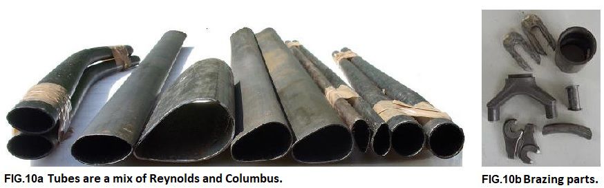
A quality tube is butted. From the outside you can't see this; the seat tube will only have a greater wall thickness between the bracket and the frontderailleur. As supplied the tube is ± 620 mm long; if we built a 50cm, and cut the wrong end to size , we cut the whole butted part off !. Well that won't happen to you (?). Reynolds frames one short butt (marked !) and a long one. The short side may only be filed fitting! So the long side should be cut to size.
Tubes used to be round. Nowadays there a many profiled tubes, some flat (less airresistance), others multiform (more frame stiffness). The framebuilder needs to work carefully then; stiff frames are hard to align. A frame of Reynolds 753 tubing can't be aligned at all, because the tube has no yielding point. The frame needs to be perfectly brazed with a 55% silver brazing rod, because the temperature while brazing, should not exceed 700 °C. The frame can't be welded . The frontfork can't be bent too. By cutting a part of the rake off, that was made in the factory before hardning, the builder can alter the trail. Reynolds frontforks are often raked at the factory; this can be specified when ordering. Columbus forks are usually straight and are bent by the builder.
To build a frame you need: 1 bracket and forkcrown, 2 headlugs , 1 seatlug, 2 front and rear dropouts, 1 small bridge, one large bridge several smalll braze-ons (for guiding cabels, bosses, etc.) and the tubing.
The steerer colomn needs to be longer than the headtube; this depends on your headset. “A-headset”-design needs a steeringcolomn without treading. Needlebearing headsets like Stronglight use a lot of space (up to 44 mm). Choose the threads 50mm longer then the headtube measured from the forkcrown; cut to size later. Check the rake and braze the forkends.
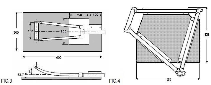
You must make a design: a drawing at full size. All angles and dimensions are known now. Make a simple jig to braze frontfork (see FIG.3). On the base plate we draw a central line. On the dropout side we use 100 mm wide spacer on the middle of the line. The steerertube often has a dimension of 25,4 mm. So the axis of the fork 12,7 mm above the base plate. Check if the rake you chose, is met by this set-up. In FIG.3 it is 12.7 + S mm; hold the steerertube with a C-clamp. Make a venthole in the forkparts befor brazing (2 mm), so the air can get out while heating. Clean and flux while setting up the jig; for brazing I use it vertical and the fork upside down. Protrude the steerertube a few mm's through the crown. This is where we will add most heat. Start adding braze at the protruding steerertube until it is coming out on the other side, so we are sure the joint is filled. Then we braze the forkparts.
If the fork needs bending after brazing , you should build a special jig. I welded a frontwheel axle on a base-plate and made a lever of 500 mm tube 30X2mm. Clamp the dropouts and bend the fork over a wooden or metal curved surface, radius about 200-300mm; don't bend too far.
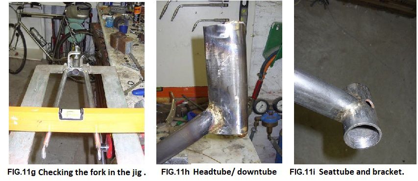
For the main frame we can make a jig as well (see FIG.4). At first I braze the headtube/ downtube joint. Headtube should be protruding a few mm's so the flux can be pushed out of the joint. Check the angle after brazing on your drawing. Next I am going to do the bracket seattube joint. Check with a straight edge if it is perfectly perpendicular. I clamp it on a flat surface, measure its height flip it over and measure the other side; if correct both sizes are the same. Then unite the downtube and the bracket. Align the headtube and seattube; be carefull you don't spill too much flux and braze in the bracket. Then I clamp the frame on the flat surface again and flip it around. Align if there are any differences. The toptube joints are last joints we make; check if the mitered tube is perfectly fitting. As you know by now , the headtube and seattube should protrude a few mm's.
Check the sizes and angles on the drawing before brazing. There must be a venthole in the headtube toward the toptube. After brazing, grind off the protruding parts. Drill a 2-3 mm hole on the back of the seattube about 40mm's from the top. Carefully cut the seattube with the grinder till you reach the hole. File and sand it inside, so it is smooth and won't scratch the seatpillar.
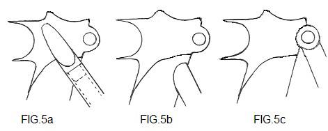
Now we going to fit in the rearforks. Watch out that the spaces for tires and chainring are in the right spot. Cut the forkblades to size. Short blades are only possible if you use vertical dropouts. Now braze the dropouts and use an old hub as spacer; carefully align and braze the forkblades. Check the height of the dropouts as this influences your groundclearence. Stick a ruler in the bracket and lay one on the rearforks; are they parallel? Are the droputs in the middle of the plane through the mainframe? If not, align ! Then we braze the bridge behind the bracket. Now the rearstays can be brazed; you can use plugs or plates (FIG.5a), mount it directly to the tube (FIG.5b) or seatclamp (FIG.5c). Don't forget the ventholes. The last important brazing is the brakebridge. Before finishing we fit the braze-on's.
For finishing we need a lot of special tools. A good relationship with the mechanic of your bike-shop might help.
1. With the headtube reamer/ race the cut the inside diameter of the headtube to 30,0 mm, and the top of the headtube is cut perfectly perpendicular to the axis. The same procedure is used at the bottom.
2. With the crownrace cutter we cut the diameter of the forkcrown to 26,4 mm and we face the top of the crown, so headset can be installed perfectly.
3. With the thread cuttingtool we align and clean the threads of the bracket.
4. Next we turn a guidesleeve in the bracket. This will help the bracket facing tool to make the outside surface of the bracket perpendicular and flat for fitting axle bearings.
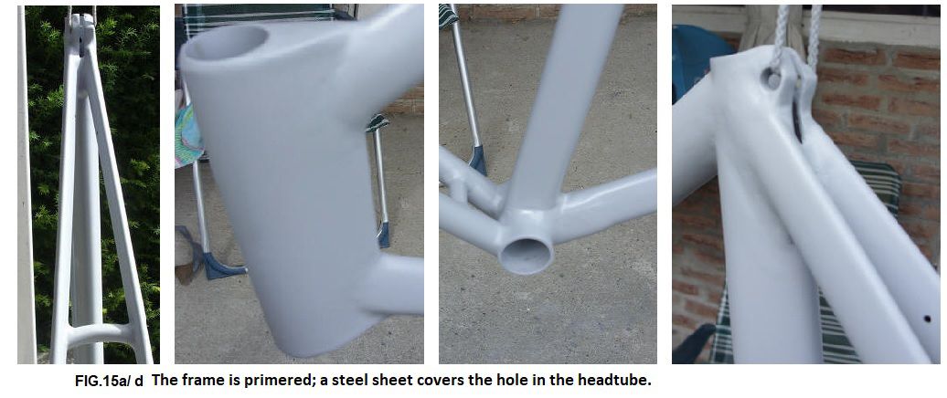
If you use a high quality bracket you might not need tools 3 and 4. Finishing the frame before spraying, will take a lot of time. Use fine sandingpaper and productioncloth. Be carefull with files; you can easily damage the thin walled tubing especially when removing residue of the flux. These can be as hard as glass. Small imperfections can be filled with tinsolder or filler. Once the frame is ready for spraying, you could built it up to see if everything is in the right place and it rides well. Changes can be made before we spray the frame; after that it will mean a new sprayjob
The era of the classical steel racers has come to an end in the nineties .......
Progress takes its toll. Thus ended the use of a reliable production method for bicycleframes. The weight of the new generation of carbon frames, is half that of the classical steel racers with lugs; lighter and stiffer: technically a great progress. But we love nostalgia. People who started their cycling carreers with tubulars and steel, often dream about the good old days. Being old fashioned, I have built those but nice, lugged steel bikes too.
We are lucky we forgot about the repairing of the tubulars, and re-trueing the wheels after breaking the chromed spokes......

The touringbike Frame: Reynolds 531, BoCaMa lugs and forkcrown, forkends Campa, bracket Roto, headset Stronglight, bars + stem 3TTT; wheels: Maxicar hubs (48 spokes), spokes DT (5 cross), rims Mavic; 6-speed free-wheel Maillard 14-28 (french threads!), chain Sedis, Dotek crankset 52-42-30, Shimano rearderailleur, Suntour frontderailleur and barend shifters, pedals Shimano, brakes CLB, Brooks B17Standard sadle.
The bike has been my mate on several cycling holidays, like Cyclotours Alps-North-South.
The last long ride was a combination of 3 descripted bike-rides: "Langs oude wegen 1& 2" the "Katharen-Basken fietsroute" and the "Groene weg naar de Middellandse Zee" in 2007, see www.pirola.nl and of course the report of that tour on the "Way" page of this site.

The racing bike Frame: Poppe&Pothoff Noblex (stainless 18/10 staal); lugs, bracket, forkends and crown are Long Shen stainless; headset Stronglight A9, bars + stem 3TTT, brakes Miche, wheels: hubs Shimano Ultegra 32 spokes, Sapim spokes, front radial and rear 3x cross, Ambrosio Focus rims. Crankset: Miche Primato 50-34 with an oldfashioned Campa Record bracketset. Pedals are Time Atac ATB-type, just like the Shimano rearderailleur and the 9 speed 11-32 cassette. The cheap Alivio works good with the Dura-ace barendshifters; the saddle is Brooks (Professional). The finnishing (?) of the bike is bare steel. The steering of the bike is very stable (small rake) en de rearfork very short. Usually I like this combination, but in the Lake District the short rearfork made climbing difficult; the ride I did: http://www.bikeit.eclipse.co.uk/localrides/ride2/index.htm . On steep hills above 25% the pressure on the frontwheel proved to be too low; pulling the handlebars sometimes resulted in the frontwheel stepping aside. Around 30% this became a real problem. Descending these steep hills is hectic; brake everywhere you can, as hard as you dare ; for the rest: god bless.......

In addition to constructing bicycle frames with lugs, it is also possible to construct frames with only solder alone. This method of building is called "lug-less soldering", "lug-less brazing", or " fillet brazing".
The Taylor brothers, (well known English frame builders), often worked in this way. The British 'Viscount' company, in the mid-seventies, used this technique for mass production. In the mid-eighties Peugeot even succeeded in automating the frame manufacturing process completely (see Fig.9a.). Yet this way of working was primarily used for bespoke frame designs by specialist frame builders (often for less conventional designs of racing frames).
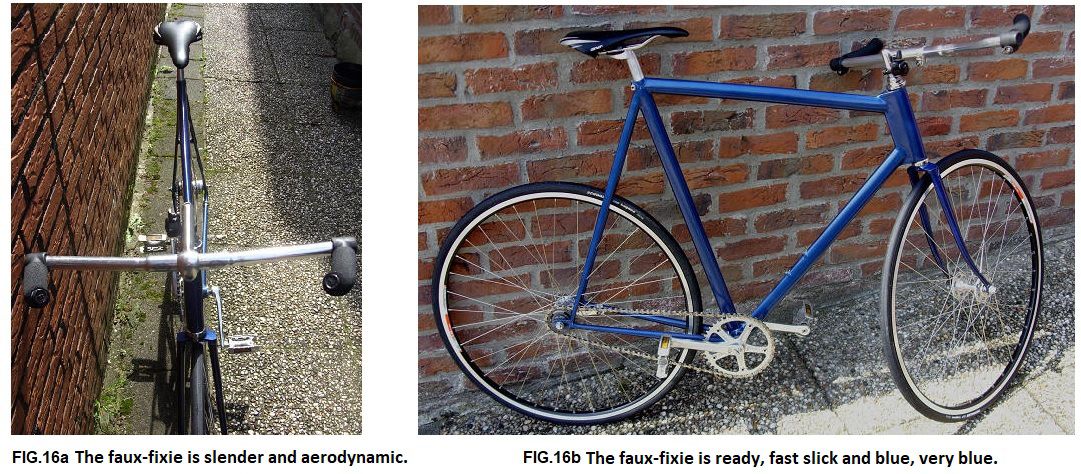
I discribe the building of a project bike, not a real time trial bike, but more a fixie: sleek, minimalist, and clean. However, it is also not a true fixie, (with a fixed-wheel, to be used on the roads) because I will ride it in a bicycle lane, and there will be a Sachs rear hub, that has an Automatic second gear and a coaster brake in it ; so it is really only a faux-fixie .......
This faux-fixie project was not my first experience with lug-less brazing. My tandems and recumbents were also brazed this way. In particular, the second tandem was significantly different from conventional forms of construction (see Fig.9c.).
The seat-tubes of tandem Number-2 were largely square profile tubes ; with the top section of both the seat-tubes containing a piece of round tube, which was for the seat post holding the saddle. The tandem frame consisted of three main parts (see Fig.9b) ; the middle section of which could be removed from the other two, to create a normal solo bicycle, (by joining the front and rear sections together without the middle frame).

Each seat-tube consists of a square tube that is 35 mm X 35 mm X 2 mm; the front part is cut away over the length between the dotted lines. The frontframe is brazed to a square tube 30mm X 30mm X 1mm. It can be hooked into the middle frame or rearframe and will be secured with two screws to the next frame section. The middle frame of course has the same square tube 30mm X 30mm X 1mm for hooking it to the rear. The tandem can be easily stored, or used as a common bike.
The solo version was mainly used for transporting our young daughter, before she could ride a bicycle herself. After a decade my wife said, she had enough of chasing around on that tandem.......
In FIG.10a. we see the frame tubes of choice ; the fork-blades are made from Reynolds '531' (the old default profile). The head-tube of the frame has been significantly altered ; it was the intention of Columbus to use a round profile head-tube. Originally there was a normal round head-tube in the Columbus tube-set ; but I chose a wing profile head-tube instead. The seat-tube and down-tube are both identical ; I will therefore have to make a seat post that can fit the oval profile of the seat-tube. The seat-stays start at around 12 mm in diameter round section, and then change into an aero profile shape. For the chain-stays I consciously chose a heavy tubing ; this provides a larger brazing surface contact area, and thus a better adhesion to the bottom-bracket shell. Moreover, this heavy tube choice improves the lateral stiffness of the frame, which can be a weak point on these types of bikes. I will also add some additional reinforcement at the junction of the frame tubes with the bottom-bracket shell.
The frame will weigh 2.3 kg, without fork (0.7 kg), (2.3 + 0.7 = 3 kg).
The design specifications in general are : normal head-tube rake of 72.5 ˚ ; seat-tube angle of 73 ˚ ; the top-tube and the seat-stays join together just below the saddle. The seat post only has a length of about 6 cm ; the horizontal top-tube length is 55 cm, and the seat-tube is 67cm long.
The main brazing parts are : the bottom-bracket sleeve, the front and rear drop-outs, and the fork-crown (see FIG.10b.). In particular, the fork-crown (made by Davis) is far too heavy; I ground a lot of it away. After all the grinding and polishing, I weighed the crown again. The whole process delivered 53 grams of weight saving ; the lightened fork-crown weighs only 192 grams instead of 245 grams (saving 22 %).
After the main part of the grinding work is done, the steerer-tube is brazed into the fork-crown. You can see in FIG. 11b. the steerer-tube protrudes slightly below from the base of the fork-crown ; this excess material is then ground down, to be smooth and flush with the surface of the fork-crown.
There will be a normal round head-tube, fitted inside the wing profile outer aero section head-tube FIG.11a; the holes in the inner head-tube serve to allow hot air to escape from the workpiece, during the heating of the hot brazing process.
On the drawing board FIG.11c, I laid-out the angles and the dimensions of the frame. The full length of the seat-tube is used ; I have shortened an old aero seat post, and adapted it to the shape of the profile of the seat-tube.
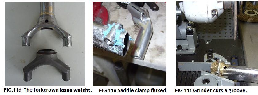
At the top of the seat-tube, I braze a small short tube where the clamp-bolt fits in FIG.11e; under the small clamp-bolt tube I drill a small hole, (the hole acts to release any stresses around the end of the slot, and stop any cracks from starting). I put the angle grinder in the stand, and with the cutting disk, I cut a short narrow slot into the top of the seat-tube, down to where the small hole was drilled earlier. The adjustability of the seat post is only about 3 cm up or down.
Next the bottom-bracket shell is worked on ; using a Black & Decker 'Power File' the shell is prepared for brazing, the shell is held tightly in the jaws of a vice, while the frame tubes are aligned, horizontally and vertically. The brazing is done while a tube is positioned vertically above the bottom-bracket shell.
The brazing is performed in two phases ; for the first phase, the connection between the parts is established, using a small amount of braze (only 1 cm to 2 cm) ; then for the second phase, the braze layer is built up, by introducing braze onto the existing drop-fixing, and more braze is gradually melted into the joint, until the joint is completely covered in braze. Where this is possible, it is visually checked immediately after brazing ; on the inside of the tube, braze must be visible everywhere. If braze is missing from even one single spot, the area must be heated up again.
While the front fork is brazed in a jig, the head-tube / down-tube connection is such that using a jig is difficult, because of the shape of the oval head-tube is awkward to grip. First, the round inner head-tube is brazed inside the oval aero outer head-tube. The down-tube extends about 1cm along the aero shaped head-tube. The angle grinder is used to cut an oval profile cut-out slot into the end of the down-tube ; the end profile shape of the down-tube is filed and polished, so that it fits well with the head-tube, and is ready for brazing.
Then a hole is made in the aero outer head-tube, at the piercing point with the down-tube, and a screw is screwed into the hole, so that the parts can be held together before brazing. This same method is also used for pinning the down-tube to the bottom-bracket. Before brazing the required grinding is difficult, due to the "wobbly table effect" ; of getting a good fit in every place of contact.
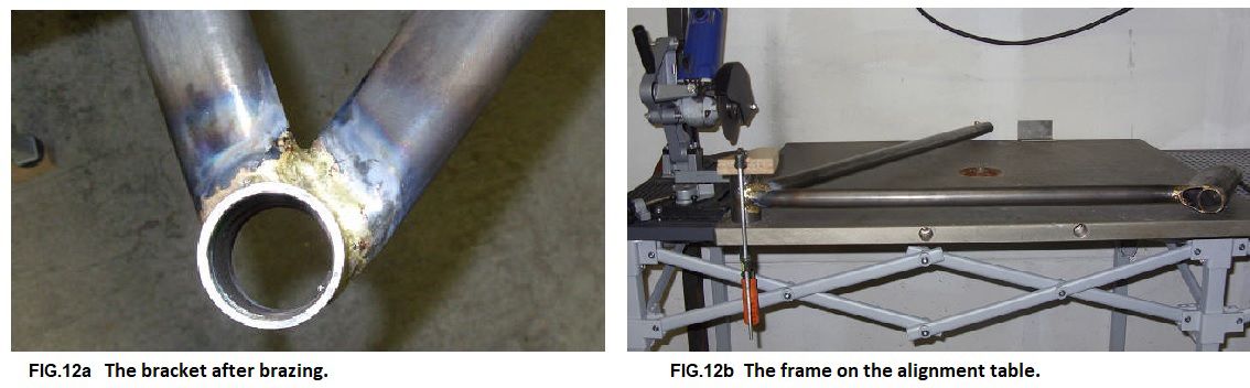
After brazing the frame is placed on the alignement table ; (originally the table was used as the bottom plate of an old saw). The frame is moved first clockwise and then counter-clockwise, and any differences are measured. The measurements show about 2 mm to 4mm of movement is needed to align the structure to the centre-line of the frame. This misalignment shows the disadvantage of not building using a jig. The first two times I exert pressure on the frame, there is no noticeable change (elastic motion). The third time I move the frame 1 mm beyond the desired value, so I have to bend it a little backwards ; and then I measure any difference again, to check.
You cannot work more accurately than your tools can measure. 1 mm is the most accurate I can achieve ; but professional frame builders can measure 10 times better to within 0.1mm ! (some professionals use expensive electronic measuring instruments.
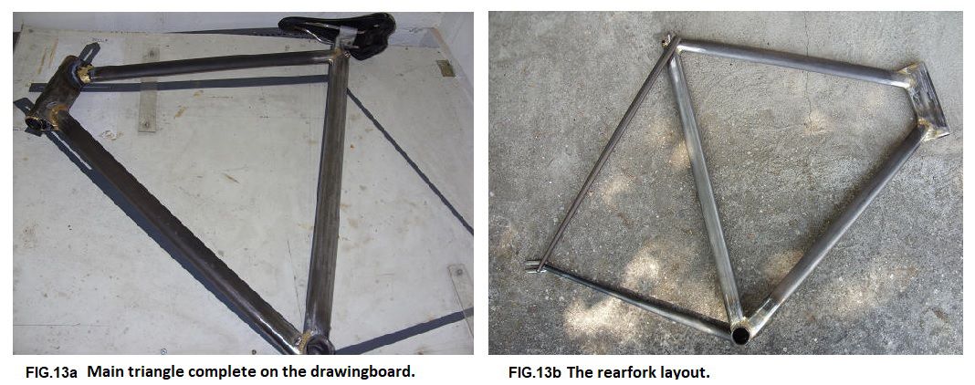
After that I make the brazing of the top-tube of the main frame triangle, the top-tube is shown in (FIG. 13a.). Here again, care has to be taken with accurate filing, fitting, and checking, etc.
In order to stiffening the bottom-bracket area, a small plate is brazed onto the down-tube (FIG. 13b.). Here I made a misjudgement ; I thought this would be easy, but there was too much slack in the fit. The braze did not want to make a good joint, due to the lack of proper capillary action, so the hot melted braze did not flow smoothly as it should have done.
Then onto the chain-stays ; I first braze on the slotted horizontal rear drop-outs. Then I put the chain-stays onto the bottom-bracket shell, and I try to make a good fit. Now the chain-stays must be suitably cut and filed to fit the bottom-bracket shell ; which takes a lot of time. I make a simple jig to hold the pieces together ; I clamp the down-tube and the seat-tube firmly in place. Using some wooden blocks, and an old rear wheel, the chain-stays are fixed in position. The frame is gripped upside down in a vice, and the brazing can begin.
After brazing the joint line, I check the position of the chain-stays to the other frame tubes with a ruler, to ensure that they are centred in the middle, (and not off to one side or to the other side), and put the frame back onto the flat table to check for any height differences ; essential careful precision work, but nothing more.
A small bridge-piece is fixed between the two chain-stays, just behind the bottom-bracket shell, to add some extra stiffness and strength to this highly loaded area. (The small bridge-piece is shown in FIG. 10b.
The mounting of the seat-stays is next and fairly simple. Fitting the seat-stays to the side of the seat-tube ; first I lock the rear drop-outs in position, and braze the seat-stays to them.
Then the top of the seat-tube is covered with brazing-flux, and fixed in the vice before brazing. The brazing at the top of the seat-tube is rather complex ; as the seat-stays should blend in with the seat-tube, to produce an elegant frame shape appearance.
Finally, I braze 2 mounts for a bottle cage onto the down-tube.
Then again I file, and I polish ; all the brazing is now done ; the rest of the work is finishing (and painting), and the final bike build up can be completed.
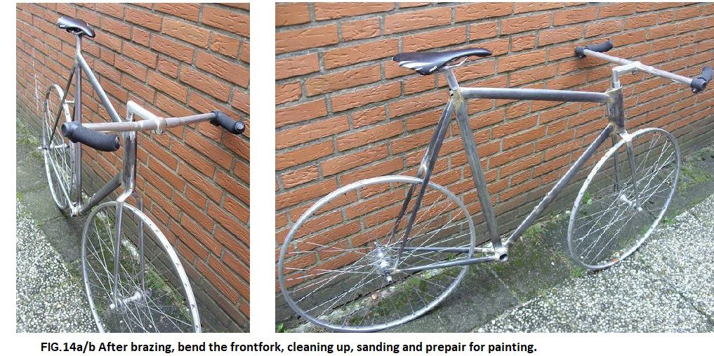
I put a classical threaded headset onto the forks, and I cut the fork steerer-tube down to size.
Now I make a few pictures of the bike, fitted with some old wheels (see Fig. 14a. + Fig. 14b.)
EPILOGUE: project E-bike
And then, after 60 years of cycling and working on bikes, it's time for your last bike. Unfortunately, that choice is not really free; an annoying progressive motor-neuron disease restricts me more and more. Putting on a tire is no longer possible without the hated tire lifters. If I try to swing my leg over a men's bike, I'll fall off the other side. My beautiful touring bike calves show clear signs of muscular dystrophy. Together with the muscles, the general condition is deteriorating; only the big belly muscle increases in size, due to the lack of energy wastage. But rejoice with me; the invention of the E-bike saves my mobility.
A low step through and a low bracket (250mm) make getting on and off less dangerous. The extreme U-shape naturally presents potential problems with strength and stiffness. The solution is the use of 2mm thick steel beams. Somewhere there were still pieces from my first workbench, which are literally recycled. The bottom part is 35x35x2mm, length 300mm. The standing U-beams are 40x30x2mm, length 700 and 500mm. These sink into the bottem beam and are baked together by brass brazing. The front and back is made from Reynolds 531. The seat tube 25.4x1,5mm, length 150mm and it is soldered into the beam. The seat post will then be 22.2mm thick. All that heavy metal has consequences: 6kg in total; the complete bike weighs 25kg.
I don't know how long I can use the bike (see FIG.17 a/b/c), so I don't buy too many and too expensive parts. The main expense is the Yose DIY Ebike kit: the rear wheel (559) with hubmotor and a 36V-15,6Ah battery. It is made by one of many Chinese manufacturers that supply Amazon. Also included in the package was the logic controller, pedaling sensor and brake levers with engine stopper. That's helpfull when you squeeze the brakes. In this case, it limits the choice to cable-actuated brakes; I mounted V-brakes. The rear hub is threaded for an old-fashioned screw-on freewheel; I chose a 14-28 seven-speed. The Ofmega cranks come with a 38 chainring; the twist grip shifter commands a derailleur from Shimano. The conversion packages do not always comply with Dutch and EU regulations. This hub motor has an additional thumb switch "throttle". The logic has a Standard mode according to the EU directive, where pedaling is necessary to switch on the motor. In the second mode you have the option to switch on the support of the motor when riding away (up to 6 km / h), via the thumb switch. In the third mode you can ride without pedaling.
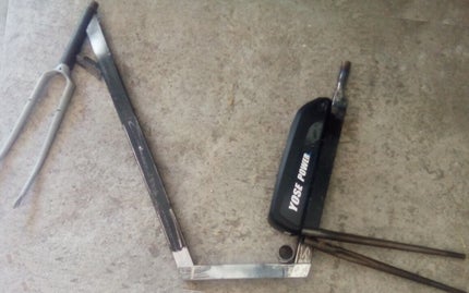
FIG.17a The U-frame lay out of the beams.
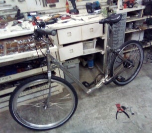
FIG.17b Partly built, to check for problems before painting.
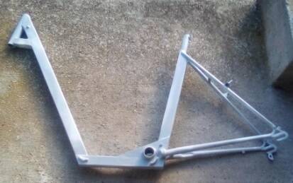
FIG.17c The frame in primer.
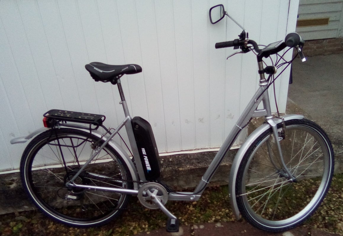
FIG.17d An E-bike for slightly handicapped old bags.
As with any project, there is an idea first: I need an E-bike with a very low step through frame. At first I bought a folding bike. It has a hub motor in the front wheel. I don't like that; when riding away, the engine input is a force beyond my control. As soon as the sensor detects movement of the cranks, the engine accelerates. Maintaining balance on a bike at low speed often requires relatively large steering corrections. A sudden acceleration can come at the wrong time. So I opt for rear-wheel drive on my bike. Technically I think a motor at the bottom bracket is the best solution. Unfortunately these conversion kits were 50% more expensive; that is why a hub motor was chosen in the rear wheel. The set was offered through a do-it-yourself importer for €360; via Amazon, the set was over €400. The only problem with mounting was the fit of the crank rotation sensor. It turned out to be made for a somewhat older Shimano standard, so I had to remove the Campagnolo axle. The manual for the control module was one of those cryptic Google translations; through "trial and error" you find out the meaning of the words.
I opted for a "water bottle battery", because the center of gravity is lower and further forward than with the "luggage carrier battery". To maintain the low entry, it came on the seat tube. The bracket is reinforced with two 3mm thick steel strips. In retrospect, I should have chosen a U-shape there. The brake mounts on the rear fork are a bit too far apart; this is solved by using a different type of V-brake behind. But I should have paid more attention.
The rearfork was brazed into a track forkcrown, and that was brazed on the seat tube. But there was not enough space for the tire, so I cut it off. I brazed the sockets of the forkcrown on the sides of seattube. And then I needed a longer bracket axle to avoid the chainwheel cutting into the rearfork.
ON THE WORLDWIDEWEB:
Scans of old flyers and photo's of bikes and parts, o.a.: http://www.velobase.com/Resource_Tools/CatalogScans.aspx ; http://www.retrobike.co.uk/ ; http://paramanubrio.blogspot.nl/p/cataloghi_6.html; http://anciensveloslyonnais.weebly.com/; http://classiclightweights.net/; http://threespeedhub.com/catalogues/; http://veterancycleclublibrary.org.uk/library/ ; http://bikeretrogrouch.blogspot.nl/
Very interesting is : http://www.richardsachs.com/site/how-frames-are-made/
Is there a future for lugs by 3D-printing? http://megadeluxe.com/videos/bike-frame-with-3d-printed-lugs-by-ralf-holleis
Internetshop (USA) for framebuilding with lugs, tubes and tools: http://www.novacycles.com/catalog/
Framebuildingcourse in the USA: http://www.bikeschool.com/home ; privat school : http://bohemianbicycles.wordpress.com/ of UK: http://www.daveyatescycles.co.uk/
More shops with nice things: http://www.bicycleclassics.com/ and http://www.classical-bicycles.com/index.htm
Building your own classic racer? Besides a somewhat outdated PDF-file: http://www.timpaterek.com/tpmanual_pdf.htm , there is a new book and instruction-DVD's.
On this English site you can buy complete sets of tubing, lugs and solder : http://www.ceeway.com/index.htm
A virtual museum in Swuisse full of old glory: http://www.speedbicycles.ch
Tens of old Gazelle racefolders: http://jvs.webklik.nl/page/gazelle
Almost all Dutch racing bikes of small and large builders: http://www.klassiekeracefiets.info/merkenlijst
There is a cross-over between lugless brazing and lugs: bilaminates, see http://classiclightweights.co.uk/builders/cb-bilam-vincent.html
Or maybe just print it? http://www.fiets.nl/2016/02/04/fiets-printen-delft/
Another guide to framebuilding: https://theframebuilders.com/wp-content/uploads/2020/10/The-Paterek-Manual.pdf
6.02 Soulcraft bikes, TIG welded 2012
9.32 RIH 1995
9.47 RIH 1995