Strength and stiffness
WHAT IS STRENGTH?
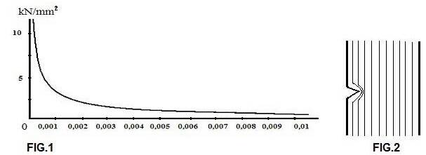
In bike frame construction people talk a lot about strength and that is why it seems as if everyone knows what is being talked about. With strength, one mainly thinks of tensile strength, i.e. the number of Newtons (1N = ± 0.1 kg) per square millimeter that a bar of a certain material can withstand up to the breaking point. But compressive strength is equally important for many structures and tensile strength is not a true constant. In FIG.1 we see a graph of the tensile strength of glass in relation to the diameter. Very thin fibers approach a strength of 14000 N / mm²; this is 10x the strength of the best frame tubes. The tensile strength is constant from 0.01mm: only 170N / mm².
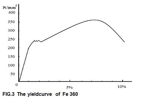
Research has shown that not only glass, but also other substances have this property. Metal fibers score poorly in these tests. This can be explained because ionic bond and covalent bond are stronger than the metallic bond. It turns out that microstructures are so strong, because there are hardly any errors (“dislocations”) in them. At a macro level, there are things that have much more influence on the ultimate tensile strength than the strength of a “perfect” microfiber. The main one is “fracture energy”. This is the amount of energy absorbed by a test bar during fracture; most solids have a low fracture energy. The strong point of metals is not their absolute strength, but their resistance to breakage. Metals are not strong but tough. Carbon fibers are much stronger than metals, but have a lower breaking energy. Scratches on the surface can cause a sudden breakage. This can be explained from FIG. 2; the lines on the figure are lines of force. The load per square mm is the same everywhere, except at the tip of the crack: there 3 lines of force run close to each other and the load is three times as high. If the total load is greater than one third of the tensile strength of the bar, the tip of the crack will exceed the maximum tensile strength and increase. Now even more lines of force will be cut and the stress for the tip of the crack will be even greater: the crack breaks through the material at lightning speed!
There are different types of microstructures in solids. Glass is amorphous, i.e. the molecules do not have regular positions with respect to each other. Most substances, including metals, are crystalline, i.e. the atoms are arranged in fixed patterns. This can be done according to three structures: 1. CSC (cubic surfaces centered, like copper, α-iron); 2. CCS (cubic centered in space like γ-iron, molybdenum); 3. HCS (hexagonal closest stack, like beryllium, magnesium).
There are different types of microstructures in solids. Glass is amorphous, i.e. the molecules do not have regular positions with respect to each other. Most substances, including metals, are crystalline, i.e. the atoms are arranged in fixed patterns. This can be done according to three structures: 1. CSC (cubic surfaces centered, like copper, α-iron); 2. CCS (cubic centered in space like γ-iron, molybdenum); 3. HCS (hexagonal closest stack, like beryllium, magnesium).
The CSC and HCS structure are maximally dense stacks: the filling level is 74%; the CCS structure has a filling level of 68%. So there are always holes in every molecular structure, the so-called interstitial spaces; these may contain other atoms. The CCS structure has larger spaces than the CSC structure, but the shape is less favorable. A carbon atom fits poorly in the γ iron crystal, but fits well in the α ‑ iron crystal. In a stack of atoms, there may be an empty space (a vacancy) or a foreign atom (a substitution). When the temperature rises, the number of vacancies increases due to the movements of atoms. Substitutional and interstitial atoms can move through vacancies (diffusion). Self-displacing dislocations develop in metals under load; these deform the grid so much that they hinder their own movement. More and more energy must be supplied for further deformation; that is why the fracture energy of metals is so high.
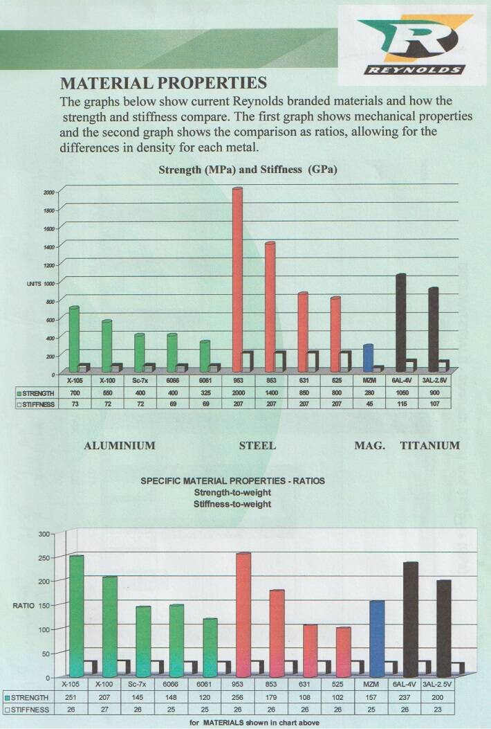
We clamp a rod of construction steel with a length of 100 mm and an area of 10 mm² in a tensile testing machine. We increase the pulling force by 50 N / mm². We take it out and measure it, after each increase. The results are plotted in a graph (see FIG. 3). The first three times the rod will stretch, but when we take it out, it turns out to be no longer. We call this elastic yield. At 2000N the rod becomes 0.2 mm longer (this is 0.2%). We call this plastic yield; we speak of the "offset" yield point or R0.2 or "proof stress".
A different phenomenon occurs at 2500N. The rod stretches while the force on it does not increase; we call this the upper yield point. In fact, the carbon atoms that had accumulated in the dislocations are pushed out. At 3000N the rod is 105mm long; If we give this bar to a colleague, as a new measuring sample, he will establish that the yield strength of this type of steel is higher than that of construction steel; furthermore, the steel has no yield point, the elongation before breaking is low, and the tensile strength is higher. This is called work hardening; it is achieved by pulling and stretching the tube over mandrels. When we bend a metal tube, strain will occur in the “outside bend” and pressure in the “inside bend”. Due to the stretch, work hardening will take place; the crystal structure of the outer bend becomes harder and more brittle. This is the explanation for the breaking of metal wire by bending back and forth. When we heat work hardened metal, the interstitial molecules will go back to the dislocations by diffusion. If there is enough time, this will also happen at room temperature (“aging”). The bicycle frame must be strong enough, so it does not permanently deform under maximum load. This is determined by the yield strength. In many advertisements the manufacturers boast about the maximum tensile strength of their metal types. Usually an insignificant value: as soon as we go over the yield point, the frame is deformed and useless! A high yield strength and a high elongation before breakage would be ideal. Unfortunately, this is a combination of conflicting traits. Some alloys (including Reynolds 753) and some fibers (including carbon fiber) have no yield strength. If we exceed the maximum load, the frame will break.
WHAT IS STIFFNESS ?
According to Hooke's law, all materials deform under tension or compression loads. If we pull twice as hard, the length elongation will double (for every material).Young phrased Hooke's law differently. It introduces a material constant E, called Young or E modulus: “specific stiffness”, expressed in Mega or Giga pascals (the pascal quantity in N / mm²). Materials are stiff if they have a high resistance to deformation. If weight is not an issue, you can make any frame stiff by using a lot of material. A bicycle must be light; that is why we also look at the relative stiffness (E-modulus divided by density). Materials with a low E-modulus sometimes can have a high tensile strength, like nylon.

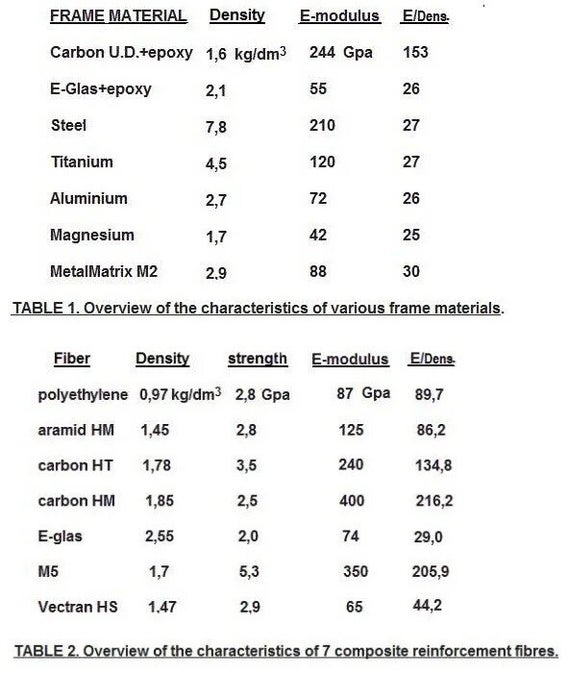
Many metals and fibers are rigid enough to build frames. Part of them are not used, due to poor resistance to varying loads; they are not strong enough, too heavy, or too expensive. If the frame builder has chosen a material, there are two methods to increase the stiffness: a larger wall thickness or a larger diameter. both result in a higher weight, but because the stiffness increases with the cube of the diameter, the builder opts for less wall thickness and a larger diameter. This makes a frame lighter and stiffer. Alloyed super steels are as stiff as low carbon steels. A thin walled tube means it is at expense of stiffness. If we look at TABLE 1, it shows that real stiffness improvement is only possible with carbon fiber. Strength-wise we can build a titanium frame that weighs half that of a steel one, but such a frame is too flexible. Again, the builder usually opts for larger tube diameters as a solution, which in turn reduces the weight advantage. Only with aluminium some progress has been made in the area of stiffness. There are aluminium-lithium alloys that are 10% stiffer (80 instead of 72 Gpa). Furthermore, aluminium can be used as a matrix in composites. Gary Klein was the first to reinforce his aluminium frames. He used boron fibers for this; this is pure boron around a tungsten core. Nowadays, particles of SiC or Al2O3 are used as reinforcement. Specialized built light frames with these “Metal Matrix” M2 tubes from the manufacturer Duralcan. Such a tube is made by heating a powder mix under high pressure to the melting point of the lowest melting component in a tubular mold. The relative stiffness is ± 15% better (see TABLE 1), but it is no longer used.
Composites of fibers and resin differ strongly in stiffness from metals: in the longitudinal direction of the fiber the fabric is the stiffest, transversely much less. With a 45 ° fabric the same number of threads are used in length and width and the stiffness is uniform. If one wants to optimize strength or stiffness in a certain direction, one can choose Uni-Directoral (U.D.) fabric with almost all threads in the length, or carbon as warp and aramid as weft. But metal has a more homogeneous composition and the production techniques are more reliable, so that the safety factor of the frame can be chosen to be lower. A wide margin must be maintained for composites.
It was not until the early 1970s that the price of carbon dropped to $ 100 per kilogram. We see the first tests of carbon frames around that time. The problem was that manufacturers tried clamping techniques to connect the tubes into a frame with aluminium lugs. This way of framebuilding proved unsuccessful. Certainly in the first generation of the American Graftek frames, some tubes came loose. These frames provide much less improvement in stiffness over corresponding aluminium tube-lug structures than would be expected on basis of the stiffness of the composite tube; the properties of the chosen connection method are of great influence.
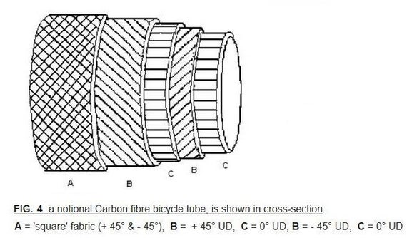
In FIG.4 the outer layer of the carbon tube (A) is made from a 45 ° fabric, this has a stiffness which is at most only a quarter (25 %) that of UD fabric (C) in the longitudinal direction (along the frame tube), but in every direction it is about the same strength. It is also possible to incorporate a few layers of UD fabric at different angles (B), to create a more robust overall structure, that can resist loads in many different directions. To optimise their structures, many modern Carbon fiber frame makers don't use only a few thick layers of Carbon fabric, but instead use many thin layers of CF fabric (this also has the effect of more accurately determining the resin composition, and the distribution of resin within the complete structure).
The Epoxy matrix should not be subjected to shear loads. This means that, in a tube-lug frame design, the fibers should be at an angle of 45 ° to the tubes and lugs. Transverse to the fibers (at 90 °), the matrix bears the load, not the fibers, The matrix has to transmit these forces to other fibers, rather than carry them itself. In many modern frames, the outer-most layer is only a coating, and not really necessary for strength. This layer makes the tube less sensitive to scratches, (and it can be used for graphic designs and patterns).
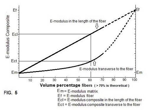
The E-modulus of Epoxy lies between 2 (adhesive) - 20 Gpa (sheet material) ; in composites it is about 4 GPa. FIG. 2a shows the different characteristics in stiffness of a composite material, as the ratio of fibre to matrix is varied. Using the example of a composite material with ; 60% fibre (E-modulus Carbon HM = 400 Gpa) and 40% resin matrix (marked on the graph with a line).
In length of the fibre the stiffness is: E composite= E fiber * Vol% fiber + E matrix * Vol% matrix , bij voorbeeld: E composite= 400 * 60/100 + 4 * 40/100 = 242Gpa
Transverse to the fibre the stiffness is: E composite= E fiber * E matrix / (E fiber * Vol% matrix + E matrix * Vol% fiber) = 400 * 4 / (400 * 40/100 + 4 * 60/100) = 10Gpa
This calculation shows an important pitfall, for novice designers of composite structures; transverse stiffness is only about 4.1 % that of in line stiffness.
There's another one : the compression loading. This is especially true for a UD fabric.
Consider for a moment ; you take a bunch of strings with a generous dollop of glue on all of them. Now, if we pull (<->) on this composite, we encounter a lot of resistance ; if we push (>-<) then this composite soon collapses. The strings cannot resist compression ; the adhesive glue (matrix) must bear all the compression, and the structure is loaded in shear of the matrix.
We now come to a material property that is called "Shear Modulus" (abbreviated as 'G'). "G" is measured in Gpa, just like the E-modulus. One important variable is the "Poisson-factor", or "Poisson Ratio", shown below with the Greek letter ν (nu) ; for Epoxy this is approximately 0.3. This is the ratio of the change of the expansion, relative to the change of compression. For example the elongation of a Cork, as it is pressed into the neck of a wine bottle, or for example the necking and narrowing of a Rubber band, as it is stretched out tight.
The compression (σ composite) which leads to collapse of the composite, is even lower : σ composite = G matrix * (1- Vol % fibers )
The relationship between the Shear Modulus (G), and the Poisson ratio ν , is expressed with the following formula : G = E : (2 . (1 + ν )) expressed in Gpa.