The craft of building wheels
SPOKES AND SPOKING PATERNS
The spoked wheel is a pre-stressed structure. The spokes of a normal bicycle are subject to a permanent tensile force of about 800N. This corresponds to a weight of 80kg hanging from the spoke. The spokes are "stretched" by about 2mm between hub and rim. In the construction they behave like a spring; by decreasing the pre-stress, they can absorb compressive forces.
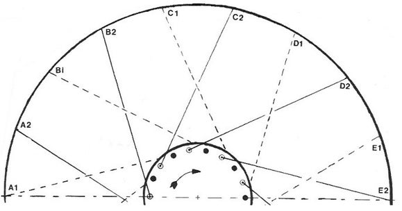
FIG.1 A rearwheel with a coaster brake hub and a "3- cross" spoke patern.
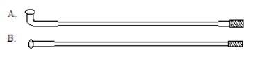
FIG.2
The first bicycle wheels were wagon wheels with wooden spokes and rims, reinforced with iron. When the wooden spokes were replaced with steel, the spoke pattern remained radial, i.e. the spokes ran straight from hub shell to rim. Such a pattern is not suitable for absorbing the forces of the riders input torque and braking. The hub will first "wind-up" the spokes, before transmitting the torque. By mounting the spokes criss-cross, a wheel was created that could absorb these forces. In FIG.1 we see the drive side of a rear wheel with brake hub. If we look at two spoke holes in the hub flange, e.g. of the spokes D2 and B1, we see:
1. The spoke head of spoke B1 is on the outside of the hub flange. So this spoke is inserted from the outside in. A1,B1,C1...etc. are called the inner spokes.
2. The spoke head of D2 is on the inside and is inserted from the inside out. A2,B2,C2...etc. are called the outer spokes. On the way to the rim, on the drive side, the spoke B1 crosses the following spokes: first D2 , then C2 and B2 .
We call this spoking pattern 3-cross .
3. We see that spoke D2 passes over B1 and C1, but under D1. We see that spoke B1 runs under D2 and C2, but over B2. This is sometimes refered to as lacing.
In some (robot) spoked wheels, D2 will go over B1, C1 and D1; B1 will run under D2, C2 and B2! It saves some time and thus money, but most builders regard it as a lack of quality.
4. The force of the riders torque (clockwise) will be transmitted through all spokes to the rim. The spokes A1, B1, etc. are loaded in tension: the pulling spokes. The spokes A2, B2, etc. are relieved; these are called the static spokes.
In FIG.1 the inner spokes are loaded in tension., while pedaling. When we brake, the force pattern is the other way around: the outer spokes are now loaded with extra tension.
The spoke length is specified in millimeters; the thickness with a different measurement: Standard Wire Gauge (S.W.G.) This is an old English indication for the thickness of wires. The S.W.G. No. 12 has a thickness of 0.104"and No. 13 becomes thinner in a step of 0.012” (= 0.305mm). From No. 14 to 17 the steps become smaller (0.008”= 0.203mm). A children's BMX bike has thick spokes no. 12; the higher the number, the thinner the spoke.
"Common city bikes" have a spoke no. 14 (2 mm thick) in the front wheel and a stronger spoke no. 13 (2.3 mm thick) in the rear wheel, because 2/3 of the weight presses on the rear wheel and the forces of the rider input torque and any brake forces of the hub, act on it. The spoke can become 2 mm longer by stretching. Spokes no. 13 are stiffer; they shrink less when unloaded. The nipples are therefore more likely to loosen. These spokes should therefore be tighter than 14's.
For 36 spoke wheels, 3-cross and 4- cross are suitable spoke patterns. The 4- cross causes problems with a low flange hub, because the spokes run over each other. It works fine with high flanges. A high flange also gives a lower spoke load than a low flange. The more spokes there are in the wheel, the more often we can cross; a 48 or 44 spoke wheel can be crossed 5 times; a 40 or 36 spoke wheel can be crossed a maximum of 4 times. A 32 or 28 spoke wheel 3x; 24 or 20 spoke wheels 2x, a 16 spoke wheel 1x.
It is often difficult to obtain rarely used spoke sizes; Although most of it can be ordered (per 100 or per bulk!), but due to delivery time and availability, we sometimes have to buy spokes that differ slightly from the desired size. There is 4mm between too short and too long. If the spokes come out through the nipples we should have taken 2mm shorter, and if we can still see the thread on the spoke, 2mm longer. The thread on the spoke is rolled, i.e. the material from the "valleys" forms the "hills"; so the thread is the thickest part of the spoke! The thread on the spoke is very shallow + or - 0.25mm. The top angle in the thread is 60° and the thread always has 56 TPI from numbers 12 to 15. This is a pitch of approximately 0.45mm, so every time the nipple tensioner goes around, the nipple moves up 0.45mm. Because many rims are only suitable for 14" nipples, there are also 14" nipples with a 13" thread now ; however, the wall thickness is minimal; these nipples are easily damaged. There are also 13 spokes with a 14 thread, a slightly better solution, provided the spokes are not too long; this thread has been cut: the nipple gets stuck on the spoke and there is a risk of breakage in the nipple, because the thread is the weakest point!
The nipples are usually made of nickel-plated brass; expensive nipples are made of strong aluminum. Cheap spokes are made of carbon steel, protected against rust by galvanizing (zinc), nickel plating or chrome plating. Zinc and nickel are good layers for spokes. Chrome is far too hard and brittle; the elastic nature of spokes will induce cracks. And cracks will lead to broken spokes. Quality spokes are made of chrome steel such as X30Cr13 (Hoshi) or chrome nickel steel such as X5CrNi18-8 (Sapim and Alpina) and X5CrNi18-10 (DT). Rich weight-weenies can even buy titanium spokes from DT. Tests of double butted spokes, compared to plain gauge, show lower peak stresses and a better absorbtion of vibration, which reduces the loosening of the nipples. And of course they are lighter.
Fiber spokes are available for special wheels, Kevlar (FiberFix), Berd spokes (Dyneema), Vectran spokes for Spox wheels and carbon from the Taiwanese CN spokes. Mavic uses aluminum spokes from Zicral (AA7075) for the Ksyrium SL. All these special spokes are expensive, sometimes €5 each and they often only fit in one brand of wheels or even only one side of a type of wheel of that brand.
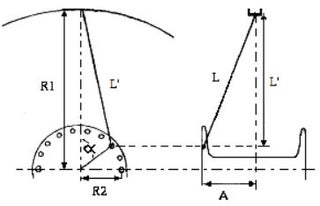
FIG.3a FIG.3b
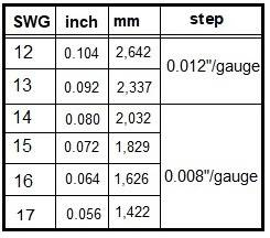
R1= half of the diametre of the rim velg incl. bottom
R2= half of the diametre of the hub (spokehole to spokehole
A= distance of the flange to the middle of the wheel
K= chosen lacing patern (0,1,2,3,4, or 5 cross)
N= number of spokes in the wheel
HUBS AND RIMS
An experienced wheel builder knows which spoke length corresponds to a specific hub/rim combination and cross pattern. For rarely used combinations he can use tables or calculate the spoke length. The spoke can become 1 to 2 mm longer by stretching and placing the spoke head in the hole in the hub flange, but this is compensated by not counting the thickness of the nipple above the rim bed.
Apply the cosine rule in fig.3a: (L´)² =(R1)²+(R2)²-2(R1)(R2)cosɑ
Apply Pythagoras in fig.3b: L²=(L´)² +A²
The spoke length is: L = √ {(R1)²+(R2)²+A²-2(R1)(R2)cos Kx720°/N}
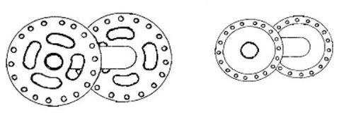
FIG.4 FIG.5
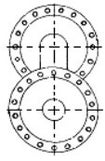
FIG.6
Hubs come in many shapes and sizes.Even if two hubs are of the same type (high or low flange, see FIG.4 and 5), there can be millimeters of difference in diameter, and therefore in spoke length.The width of the front hub is usually between 90 and 100mm;the width of the rear hub is between 115 and 140mm. Note the center lines in FIG.6
We can clearly see here that the flanges are off-set relative to each other!
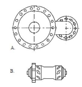
FIG.7
The height of the flange varies from 30mm for a low flange to 120mm for a drum brake. The old Sturmey Archer drum brake types even had a high and a low flange (see FIG.7A). Because the height of the brake made it impossible to braid the wheel, so-called loops were used to hook the spokes. This was not a nice system; the load on the spoke head was high because it was only partially supported by the flange. The spokes of such a wheel were difficult, because the head kept coming out of the holes; Fortunately, two equally high flanges have been chosen now. Shimano used this old idea for their Deore M555 disc brake hubs (see FIG.7B).
The main source of problems for rear wheels is the fact that they are spoked with an offset: a dished wheel, . Technically this means that the spoke tension on the right is 50-60% higher than on the left. The distance between the flanges in a rear wheel is often smaller than in a front wheel to make room for the sprockets. The heavily loaded rear wheel is therefore less stiff laterally.
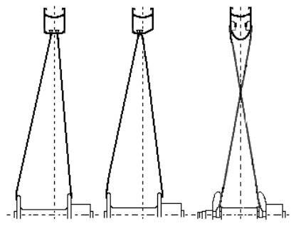
FIG.8a FIG.8b FIG.8c
Because the freewheel is on the right and the rim has to run in the middle of the frame, the spokes in the drive-side are much tighter. Especially the pulling spokes on the right are constantly working under high tension. On the left side it is mainly the static spokes that are threatened; not with too high, but with too low tension, which promotes loosening of the nipples. A method to reduce the tension difference is to install an asymmetrical rim (including Ritchey rims and Rolf wheels). Here the nipple holes are all left of center (FIG.8b). Of course, this is only a rim for rear wheels! An idea from Shimano was to cross the spokes in the vertical plane (see FIG.8c). As a result, the spoke tension on the left and right is almost the same. The spoke heads, unfortunately still with a bend, move to the rim and the nipples go into the hub flange. The hub flange then consists of aluminum blocks into which the nipples fit. We also find similar blocks on hubs for conical spokes. The weakest point of the wheel, the spoke bend, disappears in this way. The blocks do take up space on the hub; so fewer spokes can be mounted. But that's not so bad; fewer spokes save weight and air resistance. With front wheels there is much more to gain in reducing air resistance; the rear wheel sits in the wake of the seat tube. The standard rim diameters have grown "historically", i.e. mutual agreements were made in various countries between the bicycle and tire industries about the dimensions to be used. These national agreements are the cause of the enormous variety in sizes and size indications. Nowadays, almost all rims and tyres also contain so-called ETRTO sizes. An example is: 37-590. The first number indicates the diameter of the tire when inflated (37mm); the second number is the diameter of the bead, i.e. the place at which the tire clamps onto the rim. This size is better known as 26x1 3/8. The standard English 28x1 1/2 size is in ETRTO: 40x635. The standard French 28x1 1/4 size is in ETRTO: 32x622. The standard English 27x1 1/4 size is in ETRTO: 32x630. The diameter of this French 28 inch rim is smaller than the diameter of an English 27 inch rim. An English 28 inch tire does not fit on a French 28 inch rim and vice versa!
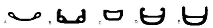
FIG.9
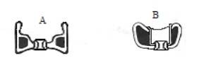
FIG.10
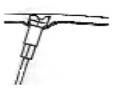
FIG.11
The main types of rims are shown in FIG.9: 9A: Westwood rim; This is used on "normal" bicycles and is made of (stainless) steel. 9B: U-rim or Endrick rim; Made in steel, stainless steel, or aluminum on cheaper sports bikes, semi-racing bikes and A.T.B.s. 9C: Tube rim: this is often used in competition racing bicycles. Usually made of aluminum or carbon, although wooden rims are also available. The tubes are glued to the rim! 9D: Box rim with horn edges; these are used on super sports bikes, racing bikes and A.T.B.'s. The horn edges prevent the bead of the tires from sliding off the rim at high tire pressure (6 to 9 bar). If it is too low, the horn edges can quickly become damaged. Modern rims lack those edges (hookless FIG.9E). In the past, nipple plates were placed under the nipples to prevent the nipple from tearing through the rim. Nowadays there is usually a reinforcing ring around the nipple hole (see fig. 10A). Sometimes this ring holds a bushing that pulls on both rim bottoms (see fig. 10B); we call this double-bushed (occurs in types 9C and D). This is the strongest construction. Westwood rims (type 9A) usually do not have a reinforcement ring; they are supplied in front wheel (14 nipple holes) and rear wheel version (13 nipple holes). With drum brakes, these rims are often capped, i.e. the spoke hole is located in a pre-formed well (see FIG. 11), which already points in the direction in which the spoke will later run. This is especially easy with high flange hubs, because the angle between spoke and rim can become very small, causing the nipple to bend the spoke. This creates an extra stress point and can lead to spoke breakage in the nipple. For capped rims, the spoke lengths should be chosen a few mm shorter than indicated in common tables. This may also be the case if the rim type deviates from the usual; A box rim will have a smaller rim diameter compared to a Westwood rim of the same tire size (from bottom to bottom, the bead is of course in the same place): therefore choose slightly shorter spokes here.
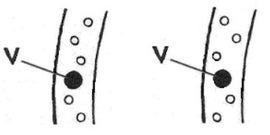
FIG.12a FIG.12b
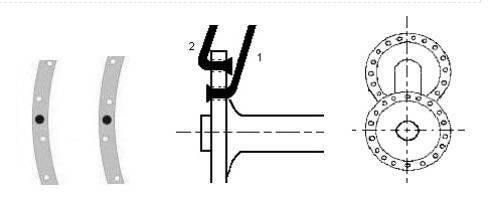
FIG.13a FIG.13b FIG.13c
The spoke nipple holes in a rim are off-center. If we look inside the rim bed, two patterns emerge compared to the valve hole: 12a: The rim has the nipple hole above the valve hole positioned RIGHT from the center: a right-hand rim; This results in a wheel with static outer spokes when spoked. 12b: This rim has the nipple hole above the valve hole located LEFT from center: a left-hand rim; When spokes, this results in a wheel with pulling outer spokes. N.B. There is no point in turning the rim.
We usually see the pattern 12a in touring and sports bikes with brake hubs; pattern 12b in (semi) racing bicycles. The number of spoke holes varies from 12 for a children's bicycle to 48 for a tandem. Because the number of spokes in the left and right flanges is the same, and there are the same number of inner and outer spokes, the number of spoke holes is a multiple of four. Racing rims are available from 12 to 40 holes. The 12 holes are e.g. on the track, or used in time trials (only in the front wheel). The 40 holes are in cyclo-cross bikes and track tandems. The standard was 36 holes, but we are seeing a shift to 32 spoke wheels. Special rims are sometimes difficult to obtain; So search and/or order! The rim width is related to the tire diameter. Wide tires go with wide rims. However, there is a lot of room for maneuver here, provided the diameter of the rim is correct. Tires that are too wide often tear along the bead; If the tires are too narrow, the inner tube may pop out.
In FIG.13a, the nipple hole above the valve hole is LEFT from center. FIG.13b shows RIGHT of center. There's no point in turning the rim! N.B. We are looking in the rim bed. The hub of a wheel has two flanges through which the spokes are inserted. The first series of spokes is inserted from the outside in (see spoke number 1 in FIG.13b; we call these the inner spokes). The second series extended from the inside of the wheel to the outside (see spoke number 2 in FIG.13b: the outer spokes). The strongest spokes in the wheel are the spokes that are inserted from the inside out. These spokes are further apart, so they can handle extra loads better. The flanges on the hub are rotated relative to each other (see FIG.13c). Note the centerline between front and rear flanges. The spoke holes in the flanges are therefore offset; this is important when weaving! N.B. When building a wheel, we always start with the inner spokes.
THE FORCES ON THE SPOKE
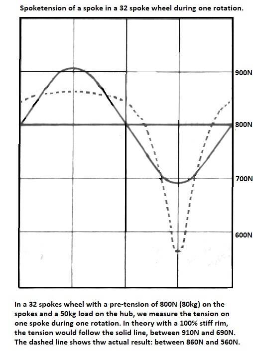
Just a theoretical experiment: we take an absolutely stiff rim and we attach a hub to two directly opposite spokes (radially). If we measure the force that the nipples exert on the spokes with a spoke tension meter while tensioning the spokes, it turns out that the tension in both spokes remains exactly the same: ACTION = - REACTION! We bring the spoke tension to 500 N (N = Newton: 1 kg is approximately 10 N). We now place this wheel upright, with the spokes vertically, and hang a weight of 10 kg from the hub. This will exert a force of 100 N. The tension in the upper spoke is not 600 but 550 N (and in the lower spoke 450 N). Both spokes absorb half of this force! This also applies to brakes and the drivetrain: all spokes absorb these forces. The more spokes, the less change in the load per spoke!
Assuming a 32 spoke front and rear wheel with spokes no. 14, the tensile force on the spoke at rest (static) is approximately 800N. We put such a wheel in a bicycle weighing 10 kg, with a rider weighing 80 kg; most of the weight will rest on the rear wheel (50 kg). The weight pushes the hub down. Because the rim yields slightly, the effect of tension reduction at the bottom is greater than that of the additional load on the upper spokes. With a 32 spoke rear wheel with 50 kg of pressure on it, the "relief" is approximately 240N and the additional load is 60N. When cycling, the spoke tension of the wheel, in each spoke, with each revolution (i.e. 500 times per kilometer), will vary between 560 and 860N.
A spoke can only transmit forces in its longitudinal direction. To transfer force from hub to rim, or vice versa, the spokes must be tight. If a spoke is subjected to compressive loads, the spoke tension decreases proportionally. This can result in the nipple loosening due to vibrations if there is insufficient pre-tension. Loose spokes are just as bad as broken spokes; they do not contribute to the strength of the wheel. The other spokes will therefore have to absorb higher changes.
Very high stiffness rims give less variation in spoke tension and are absolutely mandatory for wheels with few spokes. Some wheels have the spokes in pairs; the holes in the rim are therefore not evenly distributed. Because two spokes are now relieved at the same time, the variation in spoke tension is smaller. High spoke tensions don't lead to stiffer wheels.
Spokes are very strong; these types of steel have a tensile strength of approximately 1200 N/mm². If a spoke spoke is loaded beyond the yield limit, the prestress decreases; this limit is around 900 N/mm². For most spokes the load may not exceed 2200N! The fatigue limit is determined by resistance to varying loads: for a good spoke more than 1 million times. The spoke manufacturer Sapim even gives 3.5 million cycles for their CX-ray. Is that a lot? Make no mistake: after 2000 km the wheel has already turned 1 million revolutions. This causes spokes to break: not the high tension, but metal fatigue; fortunately steel is not that sensitive to fatigue.
In a modern 16 spoke front wheel, the spoke tension is 1000 to 1200N (the same on both sides). In dished rear wheels (see figure 8a), the spoke tension can increase considerably. On the left the tension is sometimes 900 N and on the right in the spoke screen on the drive side even 1500 N! Here we are at the limit of what is permissible. The variation in weight load is the same for each spoke, and is independent of the cross pattern (just of the number of spokes). In addition to static tension and weight load, impact loads also act on the spokes. Riding through potholes and against curbs not only produces a very high load, but above all decreases (!) of the spoke tensions (> 250N!). If the static tension of the spokes is too low, the nipple will loosen due to these force changes.
Wheels are stiff relative to the tire. However, bringing the tires or tubulars to 8 to bar can reduce the tension of the spokes by 30 to 40N. N.B. The forces above are independent of the cross pattern, so are the braking forces of rim brakes do not pass through spokes and hubs!. This braking force works in two places; at the top of the rim near the brake pads and under the tire. The reaction force comes from the front fork. This pushes the hub forward; the front spokes are relieved and the rear spokes are additionally loaded. The static spokes are subjected to the least load while riding, which is why braking forces from rim brakes hardly play a role. What can play a role is shifting the weight. The pressure on the rear wheel decreases when braking and the pressure on the front wheel increases; in the extreme case, all weight is on the front wheel.
Torque induced tensions and braking forces from hub- or disc brakes do act on the spokes; now the static spokes are loaded in tension. The spoke load will partly depend on the cross pattern. Braking forces are sometimes twice as high as riding torque forces. It is recommended to use strong spokes with brake hubs or disc brakes, make the outer spokes static and cross them as often as possible.
THE SPOKING PATERN AND DISTRIBUTION OF FORCES
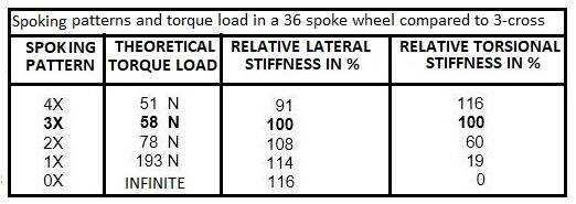
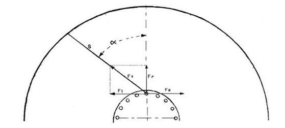
FIG.14
The spoke load due to the torque depends, among other things, on the rider, gear and hub flange height. If a 75 kg combination of rider + bicycle goes up an 18% slope, the theoretical force for the propulsion is 750N x0.18= 135N. The torque delivered is : 135N x 0.335m (radius of the wheel) = 45Nm. This same torque passes through the hub flanges and the spokes. Suppose the radius of the flange is 0.025m, then the force there is: 45Nm: 0.025m= 1800N! In our example with a 5 cm flange and 36 spokes, the additional load of the torque would be 50N per spoke, if the spoke were exactly perpendicular to the center line through the hub flange.
In a 36 spoke wheel, 3-cross, the theoretical values are slightly higher: approximately 58 N. We use this value as a standard for the calculations in table I. We give the relative lateral stiffness and relative torsional stiffness compared to 3-cross.
When we look at a pulling spoke S (see FIG.14) in a 3x-cross wheel, we see that the riders force Fa, acts perpendicular to the center axis of the hub. However, the spoke S can only absorb forces in its longitudinal direction. A force Fs is created in the spoke, which transmits the torque, the tangential component Ft, prevents the wheel from winding up.
Ft is always equal to Fa, but opposite; Fs becomes as large as necessary to get Ft= -Fa . With a 3-cross wheel, angle ɑ is approximately 60°, so Fs = 50N : sin60°= 58N. A radial component Fr is also created, which improves the lateral stiffness. As angle ɑ increases, Fr and Fs decrease in magnitude. If angle ɑ is ninety degrees, Ft= Fs: then the spoke load is minimal. Unfortunately, Fr = 0, which is at the expense of lateral stiffness.
If ɑ is greater than 90 degrees, the spoke load increases again, while Fr becomes negative. The lateral stiffness therefore deteriorates rapidly. As the angle ɑ decreases (a less cross pattern), Fs and Fr increase, because Ft remains the same! The spoke load due to driving forces (torsion) therefore increases. In a radially spoked wheel, Fs is theoretically infinitely large. In practice the hub will "wind up" e.g. 2°. Then Fs = 50N: sin2°= 1433N. A wheel in which torque or braking forces are applied to the hub, should not have radial spoke pattern! In practice, the spoke loads for the "drive side" are higher. The hub flange on the drive side absorbs more force because the stiffness of the hub is limited. With a rigid hub, e.g. the Sturmey Archer 3 gear hub, a spoke from the right screen will absorb 60% and a left one 40%. With an aluminum hub the values are much less favorable; here the right takes up 85% and the left 15%. For 36 spoke wheels, 3x and 4x cross are suitable spoke patterns. The 4X cross causes problems with a low flange hub, because the spokes run over each other. It works fine with high flanges. A high flange also gives a much lower spoke load than a low flange. The more spokes there are in the wheel, the more often we can cross. A 48 or 44 spoke wheel can be crossed 5 times without the angle ɑ is exceeding 90 degrees. A 40 or 36 spoke wheel can be crossed a maximum of 4 times. A 32 or 28 spoke wheel 3x; 24 or 20 2x, a 16 spoke 1x.
N.B. angle ɑ is ± 30° for a 16 spoke wheel crossed once. The theoretical load due to driving forces is high: (1800N:16): sin30°= 225N per spoke! The actual forces in the right screen are higher: ± 400N. We can spoke a front wheel without a brake hub or disc brake in every possible way. The lightest, strongest and stiffest are radially spoked wheels. We can safely use 32 or fewer spokes in these wheels. Building rear wheels the matter is more complicated. We should strive to avoid dished wheels. This can be done by using wide hubs and rear forks, or by building asymmetrical frames. For a 36 or 32 spoke wheel, 3 x crossed is desirable. With small wheels, such as 20 inches, I settle for fewer spokes and fewer crosses. Otherwise the spoke will be too slanted in the rim (danger of spoke breakage in the nipple). Small wheels are stronger and stiffer anyway; they also have a lower spoke load (smaller rider force and more revolutions per minute).
BUILDING BIKE WHEELS
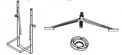
FIG.14b The tools of the trade.
We describe the traditional spoked wheel here. There are variations on this way of working. If you follow a particular description, stick to that method; following more descriptions at once leads to confusion and errors.
There have been many new wheel designs over the past 40 years. The trend towards stiffer rims and fewer spokes is clear. The steps to disc brakes and wider rims and tires result in somewhat heavier wheels. The life of the wheel will increase by eliminating rim wear. Because the braking forces now go from hub to rim, radial spoking of wheels is no longer possible . The number of spoke holes varies from 12 for a children's bicycle to 48 for a tandem. Because the number of spokes is the same on the left and right, and there are the same number of inner and outer spokes, the number of spoke holes is a multiple of four. The old standard was 36 holes.; now 32 spokes is more common.
N.B. Some modern variants have more spokes on one side.
Always start all cross patterns from the valve hole. Otherwise, a crossing of spokes above the valve sometimes occurs, which makes inflating the tire difficult.The braiding for all spoke patterns is virtually identical.For a certain spoke length + hub + rim, the spoke pattern is actually fixed.An experienced wheel builder knows which spoke length corresponds to a specific hub/rim combination and braid pattern.For rarely used combinations he can use tables or calculate the spoke length.At the bottom of this page there is a formula to calculate spoke lengths and an app in Excel.We can spoke a front wheel without a brake hub or disc brake in every possible way.The lightest, strongest and stiffest are radially spoked wheels.We can safely use fewer spokes in these wheels.With rear wheels the matter is more complicated.We should strive to avoid the umbrella spokes.This can be done by using wide hubs and rear forks, or by building asymmetrical frames.For a 36 or 32 spoke wheel, 3 x crossed is desirable.With small wheels, such as 20 inches, I settle for fewer crosses and fewer spokes.Otherwise the spoke will be too slanted in the rim (danger of spoke breakage in the nipple).Small wheels are stronger and stiffer anyway;they also have a lower spoke load (lower driving force, more revolutions per minute).
SPOKING : 0 AND 1-CROSS
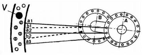
FIG.15
There is actually little difference between building a front wheel or a rear wheel. In a front wheel without a brake hub or disc brake, we can use any braid pattern. At a rear wheel, at least one screen must be crossed, preferably several times; this depends on the number of spokes as we have just seen. The simplest way to spoke wheels is radial (0x crossed). It can be done in three ways: 1. All outer spokes (all spoke heads inside) 2. All inner spokes (all spoke heads outside) 3. Alternately.
I wouldn't know of any argument for the third method. The second method is, according to some, more beautiful. The first method is best; the wheel is about 10% stiffer because the spokes are further apart and the spoke head is better supported by the flange, reducing its strain. This is a weak point with radial wheels; not only breaking spokes, but also hub flanges! These are heavily loaded with radial spokes. However, a radial wheel is aerodynamic, super light and super stiff. N.B. Shimano does not provide a warranty on the standard hubs with radial spokes!
It does not matter whether the rim is left or right. The picture in FIG.3 happens to be on the LEFT; For a right-hand rim, read RIGHT wherever it says LEFT. Insert the spokes from the inside out through flange A. Always start all braiding patterns from the valve hole. Insert the first spoke to the LEFT of the valve (a1). Then to LEFT a2, a3 etc., until we return to the valve. We now look along spoke a1 to flange B (see FIG.3), and we choose the spoke hole to the LEFT of a1 on flange B. In this way we insert the first spoke from the inside out. We install this spoke to the LEFT of a1 in the rim between a1 and a2 in the hole b1. Now we insert the remaining spokes into the flange and install them in b2, b3, etc., until we reach the valve again. If everything works out well, we can tighten and align the wheel. The 1x cross braiding pattern can also be braided using only the outer spokes. Based on FIG.3, we simply insert the first spoke at a2, and the second at a1. This way we go around the entire rim again. Of course, on the other side the first spoke must be inserted at b2, and the second at b1. With a 1x crossed braid pattern, we skip a hole on the rim (for example b1 between a1 and a2). We can now say that the low cross includes one spoke hole on the rim. This number increases as crossbreeding occurs more often. With 2x there are five spoke holes on the rim, with 3x nine, and with 4x thirteen.
SPOKING WHEELS: 2-,3-,4- AND 5-CROSS
The spoking for all these spoke patterns is virtually identical. For a certain spoke length + hub + rim, the spoke pattern is actually fixed. We assume a 36 spoke hub (this eliminates 5- cross!) and a LEFT rim. If the wheel is suitable for a cassette or freewheel, the spokes on the drive side should be shorter; usually this is a difference of 2mm. These spokes are subjected to a 40 to 50% higher tension. BUILDING WITH A REAR HUB WE START ON THE DRIVE SIDE. The flange we start with is called flange A. (N.B. If we have a right-hand rim, then where it says LEFT, read right! The wheel is also spoked clockwise).
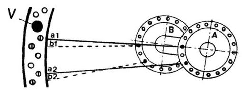
FIG.16
We insert spoke A1 (see FIG.16) from the outside in and attach it to the spoke hole in the rim LEFT next to the valve hole. We now skip a hole on the hub and insert the second spoke (A2) from the outside in. We now skip three holes on the rim and mount the nipple in the fourth spoke hole to the LEFT of the valve. We continue like this until side A is full: nine spokes!
As we see in FIG.3a, the spoke holes on the other flange (B) are slightly offset. We draw an imaginary line through the hole in the hub flange A in which A1 is located. In the hole on hub flange B that is to the LEFT of A1, we insert the next spoke (B1) from the outside in. We install spoke B1 to the LEFT of A1. For mounting B2, we skip another hole on flange B and three holes on the rim. B2 goes to the LEFT of A2, etc., until there are also nine spokes in flange B.
We keep side A in front of us, and now turn the hub COUNTER-CLOCKWISE. Now insert the first spoke to the LEFT of A1 into the hub, from the inside out. Turn this spoke to the LEFT so that it crosses 2, 3, or 4 spokes of screen A. This depends on the braid pattern you have chosen!! We pass this spoke under the last one and install it in the correct nipple hole in the rim (A side!). We continue in this way until flange A is full. If we have worked properly, the spokes will now be in neat groups of three. We now insert the spokes from the inside out through flange B. Cross again here and pass under the last spoke. There is only one correct installation possible, if it does not work out, then a mistake has been made somewhere; this often means starting over again.
TENSIONING THE SPOKES
We start tightening all the nipples with a screwdriver until one thread is still visible on the spoke. There may already be tension on the spokes. If not, turn all spokes, round by round, half a turn until there is tension. We always work from the valve! If there are very many rounds, the spokes are too long and will come out through the nipple. This causes flat tires, so use shorter spokes or cut and file the spokes. As soon as there is tension on the spokes, we exchange the screwdriver for a good nipple tensioner. If all spokes were tightened equally and the rim was completely round, the wheel will also be perfectly round; this is often not the case. If there is a lot of sideways blow, I first remove it roughly. If the rim needs to be turned to the right, tighten the right spokes over the section in question by half or a quarter turn, and loosen the left spokes by half or quarter turns. N.B. When we tighten only the right spokes, we are actually introducing a height stroke! Once the wheel is a bit straight, we will check for height bumps. "Dents" are more difficult to remove than "bumps". Remember that the hub transmits the forces on the spokes to the other side of the wheel. While you tighten the spokes on the left and right at a bump, the opposite spokes should loosen; otherwise there is a good chance we will go from an "ovoid" to an "elliptical" wheel. For example, in the case of a dent, loosen 2 right and 2 left spokes by half a turn, and tighten all others by a quarter turn. Deformation can sometimes remain at the weld (often camouflaged by a sticker). We now take a wheel hub aligner and check whether the rim is in the middle. This is a simple bracket with an adjustment screw in the middle; first hold one side against the rim and turn the adjusting screw up to the hub. Then hold it on the other side: the adjusting screw should now touch the hub exactly again. If this is not the case: tighten all spokes on the side where the rim should go, and loosen the other side proportionately. Once the height strokes are out, we will remove the remains of the side strokes. If the rim no longer has any vertical run-out or side run, and is still in the middle, we apply final tension to the spokes. How tight is that now? Tight! Just squeeze the wheel of a good professional. Spoke tension meters are available to better control the process. When the wheel is at final tension, tighten and loosen all spokes a quarter turn; the torsional stress will disappear. Just check one last time; then put the tire on and off you go. After about 500 km we put the wheel in the aiming stand again. If the spokes were quite tight (and no accidents occurred) the wheel is still perfect. Some wheel builders then tighten their spokes by half a turn. With a good wheel the tolerances are very small: ± 0.2 mm. Especially when repairing wheels that have been used for a long time, it can happen that a nipple is turned "around". There is no other option than to remove it with pliers and install a new nipple. Don't make the mistake of loosening or tightening other spokes to straighten the wheel. This causes very irregular spoke tensions; one of the main causes for spoke problems. Such a wheel rarely becomes truly straight and is prone to spoke breakage. A bad wheel sometimes causes problems within 5,000 kilometers. If more than 2 spokes are broken in a wheel, I re-spoke it (if the hub is worth it). I use new spokes and almost always a new rim; a used rim is never really round again.
SPECIAL WHEELS
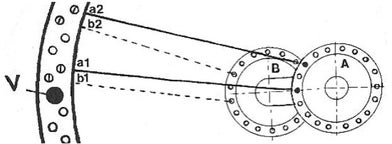
FIG.17
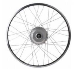
FIG.18
About aero-wheels: https://www.youtube.com/watch?v=lwrCrU4KG-I
Spoke heads often bear markings:
As we have seen, according to our "building recipe", a right-hand rim results in static outer spokes and a left-hand rim results in pulling outer spokes. To get the outer spokes in a left-hand rim static, we do the following (see fig.17). Insert A1 from the outside in, into the second nipple hole, to the right of the valve. Skip one hole on the flange, and 3 holes on the rim (both to the right!). Continue working clockwise until the first 9 spokes are inserted. We now insert spoke B1 (note the center line: to the left of A1!) from the outside inwards and mount it next to the valve hole. Reassemble B2 etc. clockwise. We now take side A again and turn the hub clockwise; We now insert a spoke from the inside out between A1 and A2. Depending on the chosen cross pattern, cross and pass under the last spoke. I expect that you now know how to proceed and also how to make a right-hand rim with the outer spokes pulling!
The spoking method described here is not the only option for building wheels. In various videos and descriptions by others, variations on my way of working are used. There are more good solutions, but wrong choices are also made. In the wheel of FIG.18 with a Nuvinci stepless gear hub, the builder opts for too many crosses. This causes the spoke to have a sharp angle with the rim and the nipple will exert one-sided pressure on the thread of the spoke. This bending strengthens the "notch effect" and leads to spoke breakage in the nipple. You can alleviate these kinds of problems a bit by making a kink in the spoke, 20mm from the thread; but that is a poor remedy and very ugly at that.
The "snowflake" wheel (FIG.19) often has this problem too; this wheel was re-invented many times in later years.
Spoke thicknesses were fairly standardized over the years. Unfortunately, this practice has come to an end and we see 2.16mm spoke thickness coming from China (with 3.6mm nipples); an abomination, is nothing sacred anymore?

10.25 About spokes nipples and threads. 21.07 A tour at DT Swiss.
The automation of building wheels.
In the 1970s and before, the spoking of bicycle wheels were a test during the examination for the bicycle repair course. The candidate was given a rim, a hub, spokes and nipples, and half an hour to make something of it. But the time needed for assessment by the examiner and the disassembly of the wheel were subtracted from that time; the next candidate used the same material. In those days, it was customary in the bicycle trade to charge half an hour of assembly costs per wheel. In the bicycle industry, people were building wheels all day long. The supply of materials and the removal of the wheels were arranged. They were large series with the same components. These employees were often very skilled, six wheels per hour was no exception; it was boring work. With the rise in wage costs and the increase in the mechanization of labor, managers were thinking about building a machine or robot that can spoke and align wheels. Technically it is quite a challenge to come up with such an arrangement. But the machine must compete with an existing practice, i.e. the manufacturer must demonstrate and/or guarantee that there is an economic advantage in using that machine. The approach of not wanting to do everything at once has proven to be beneficial for the commercial development of these machines. Inserting spokes into the hub flanges, remained manual work for a long time. Spoking the wheels, i.e. passing the spokes under each other at the last intersection, also often requires human input. This operation takes a little more time and the production speed decreases as a result, but many limitations from the early years have now been resolved. In general, the spoke tensions on robot spoked wheels will be higher, sometimes 20-25%. For the bicycle factory, the robot's susceptibility to failure, depreciation + maintenance, and the quality of the wheels produced are of course the most important factors. A patent application and a working prototype is at most a start, but certainly no guarantee for commercial success in the industry.
.Applying for a patent is not an easy task. In this first example, there is even a five-year period between application and patent grant! It is an American patent of the Herr machine factory from Ohio, but there has probably never been a bicycle factory that used this machine. Looking at the drawings, it looks complicated and therefore expensive.
The British Patent Office took 2.5 years to approve B. Sargent & R. Dressler's patent. Both gentlemen were linked to Tube Investments, a firm that included Raleigh, and later Gazelle. The unions blocked experiments with automation in the 1960s. Raleigh was not known as an innovative company.
In 1968, the French company Motobecane applied for a patent in the USA for a spoke robot. It all looks like an idea, not a design. They may have tried to sell that idea; I don't know whether there was any experimentation in France. In any case, no further development is known.
A 1969 USA patent application by "Damman et al". Mr. C. Damman became one of the founders of Holland Mechanics; this company will play a major role. Gazelle will be the first factory to actually use these spoke machines. Partly automated production lines were developed, which delivered real savings. Over the years, Holland Mechanics has managed to grow into a market leader with branches all over the world.
The manufacturers of hubs, rims, spokes and nipples have adapted their products over the years to improve the use of robots. This means, among other things, that the holes in the hub flanges become somewhat larger. This reduces the support of the spoke head; Technically this is a stress raiser and can cause spoke breakage at the head or bend. This is the most common damage in bicycle wheels; progress is not always an improvement.
When the spoke when is tightened, it rises in the nipple, and the head of the robot's screwdriver is pushed away. To prevent this, the spokes of robot spoked wheels are in this case 1-2mm shorter than hand spoked wheels. Especially with aluminium nipples, this creates an additional risk of breakage in the nipple; To overcome this, we now also see nipples with a Torx or hexagon head. In the more expensive wheels, the nipples are provided with micro-capsules of glue. During building and straightening, this acts as a lubricant and after hardening it prevents unwanted loosening.
1.13 Hub filling station.
9.47 Lacing wheels with human input.
0.52 A robot with four trueing hands.
2.52 A trueing robot working.
Compettitors of Holland Mechanics, Shuz Tung https://www.youtube.com/watch?v=ECr7c5li6Z8 and Mach1 https://www.youtube.com/watch?v=-d-jeuGErGE&t=792s etc..